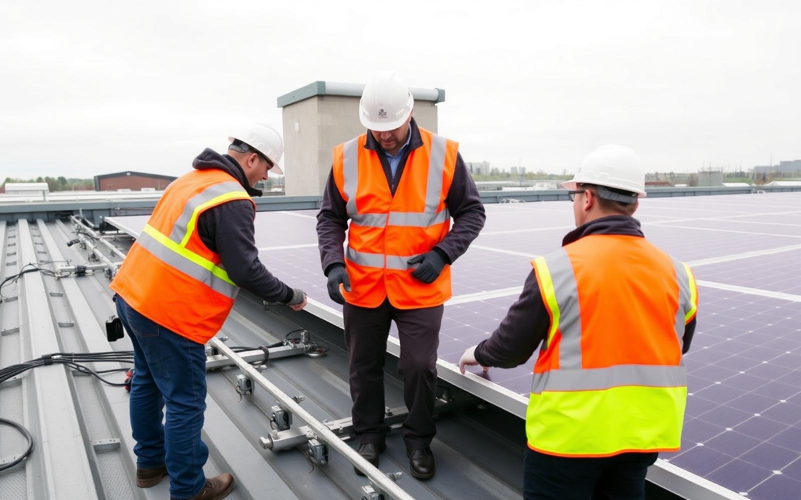
Fire-risk assessment
Review the premises fire-risk assessment before design and again after installation. Consider how the array changes ignition sources, fire spread, escape, smoke control and firefighter access.

Commercial solar fire safety
A practical guide to reducing fire risk before installation, controlling work on site and giving building teams and emergency responders the information they need.
Fire risk across the asset life
A commercial solar array introduces permanently energised DC equipment, cabling, connections and controls to a building. Good design reduces the chance of ignition, limits the consequences of a fault and preserves safe access for maintenance and emergency response.
The right controls depend on the premises. Roof construction, fire compartments, stored materials, hazardous processes, smoke ventilation, site access and the cost of interruption should all shape the project from the outset.
A controlled process
Review the building fire strategy, roof construction, hazardous areas, business interruption exposure and emergency arrangements.
Coordinate the array, compartmentation, access routes, electrical protection, isolation, detection and firefighting considerations.
Control workmanship, temporary hazards, hot work, housekeeping, cable protection and every penetration through fire-resisting construction.
Test the system, train the building team and provide clear drawings, labels, shutdown instructions and emergency information.
Inspect, test and monitor the installation, record defects and keep access, ventilation and emergency controls clear.
Plan before design
The project brief should explain how the premises is used, how a fire could develop and what the organisation cannot afford to lose.
Review the premises fire-risk assessment before design and again after installation. Consider how the array changes ignition sources, fire spread, escape, smoke control and firefighter access.
Where flammable gases, vapours, dusts or other dangerous substances may be present, assess whether inverters, switchgear or electrical equipment affect hazardous-area controls.
Confirm the roof build-up, insulation, fire resistance and load capacity. Keep mounting systems, panels and unprotected cables clear of fire compartment lines and movement joints.
Plan for fire, power loss and restricted site access. Identify critical operations, alternative power or premises, specialist contacts and the decisions needed to restore the business safely.
Test the continuity plan, not just the equipment.
A tabletop exercise can expose missing contacts, unclear decisions and unrealistic recovery assumptions before an incident occurs. Record actions and update the plan.
Fire-conscious design
Layout and electrical decisions should help prevent a fault becoming a major property loss.
Solar modules can continue producing DC electricity whenever exposed to sufficient light. Isolating the building supply does not automatically make every panel and cable safe.
Divide large arrays into manageable zones with clear panel-free access routes where the site strategy requires them.
Keep panels clear of smoke vents, roof plant, escape routes and areas needed for inspection, repair or firefighting.
Select compatible, independently tested modules, mounting systems, connectors, inverters and protective equipment for the environment.
Route and support DC cables to reduce abrasion, movement, heat, hidden damage and exposure to combustible materials or vermin.
Protect penetrations through walls, floors, ceilings and compartment lines with an appropriate tested fire-stopping solution.
Locate inverters and switchgear in cool, dry, clean and accessible areas, away from storage, impact, flood and combustible surfaces.
Coordinate earthing, bonding, surge protection and the existing lightning-protection system through competent electrical design.
Provide correctly rated AC and DC isolation, warning labels and a site-specific means for emergency responders to make internal circuits safer.
Installation controls
Define responsibility across the roof, structural, electrical, fire and principal-contracting teams. Design changes must be reviewed rather than improvised on site.
Use site induction and permit-to-work arrangements. Keep escape routes available, control access and prevent damage to panels, cables, roof coverings and fire-resisting construction.
Avoid hot work near the installation wherever reasonably practicable. Where it cannot be avoided, use a formal permit, suitable precautions, supervision and post-work fire watch.
Remove packaging, cable offcuts and other combustible waste at the end of each work period. Do not allow materials to accumulate beneath arrays or around electrical equipment.
Handover and emergency readiness
The responsible building team should understand normal operation, warning signs and shutdown actions. Emergency responders should not have to discover the system layout during an incident.
A current site plan showing arrays, cable routes, inverters, switchgear and isolation points
The main electrical intake, distribution equipment and fire-alarm indicator panel
Details of fire suppression, smoke-control and ventilation systems relevant to the area
Known hazardous substances or unusual operational risks on the premises
Clear access routes for emergency vehicles and arrangements for opening gates or barriers
Named site contacts who understand the installation and can support emergency responders
Prominent signage identifying that solar PV is installed and that DC equipment may remain live in daylight
A tested emergency shutdown and isolation procedure, with routine test results recorded
Consider early fire-service familiarisation.
For larger or more complex sites, discuss whether the local Fire and Rescue Service should be invited to review access, water supplies, array locations, isolation and other site-specific hazards.
Inspection and maintenance
The maintenance programme should reflect the installation, environment, building use and equipment condition. Competent specialists should define the interval and scope rather than relying on a universal schedule.
Planned visual and electrical inspections at intervals set by a competent risk assessment, manufacturer instructions and current requirements
Thermographic checks where appropriate to identify abnormal heating in modules, connectors, junction boxes, inverters and controls
Prompt investigation of alarms, shutdowns, unexplained loss of output, damaged insulation or signs of arcing and overheating
Removal of leaves, nests, litter and deposits without enclosing the ventilated space beneath panels
Checks after storms, lightning, heavy snow, impact or roof work that could have disturbed the installation
Routine testing of emergency isolation, fire detection and any associated warning or monitoring arrangements
Control of later roof work through permits, current drawings and contractors who understand the live DC risk
Recorded servicing, defects, corrective actions and component disposal through suitable authorised routes
Current requirements
Applicable requirements may include fire-safety and building legislation, electrical installation rules, hazardous-area duties, product and installation standards, planning conditions and site-specific insurer requirements.
Historic guidance can inform a risk review, but it should not be treated as proof of present-day compliance. Ask the project team to identify the current editions, responsibilities, approvals and evidence that apply to your building and system.
We can help coordinate roof suitability, design responsibilities, installation controls, handover evidence and the long-term operating plan.